Overview
- Major assumptions: depletion approximation, this is the region of no electric field. Therefore, Poisson's equation equal to zero, and drift is zero.
- When solving for current, only consider diffusion, recombination, and generation. Diffusion has been previously solved for. Recombination and generation are solved for using the continuity equations.
- The general solution for the continuity equations gives the recombination (U) and generation (G) under certain situations within the solar cell. Based on the region's boundary conditions, the specific particular solution is given.
In Regions I and III on the previous page, the depletion approximation states that there is no electric field. Therefore, Poisson’s Equation becomes zero, and the drift term in the transport equation (q μ nnE or q μ p pE ) also becomes zero. Minority carriers in the quasi-neutral regions move only by diffusion.
The transport equations then become:
![]() (1a)
(1a)
![]() (1b)
(1b)
The continuity equations remain:
![]() (2a)
(2a)
![]() (2b)
(2b)
|
For electrons, differentiating (1a) above and substituting into (2a) above gives: |
For holes, differentiating (1b) above and substituting into (2b) above gives: |
|||||
|
|
|||||
|
|
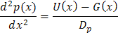
Equations (3a) and (3b) are general under steady state conditions as long as the depletion approximation holds (which assumes low injection) and as long as drift and diffusion are the only transport mechanisms. For steady state and low injection, these are the equations that must be solved to determine the electrical characteristics, of the IV equation, of a device. The solution to these second order differential equations involves firstly finding equations for U and G to determine the general solution to the differential equation, and secondly determining boundary conditions to find the particular solution.
Dominance of the minority carrier currents
In either Region I or Region III, the total current consists of two current components, Jn (the current composed of electrons) and Jp (the current composed of holes). However, we will solve only for the minority carrier current in each material, since the recombination of minority carriers controls the current flow. Later, we will also calculate the majority carrier currents Jp (in p-type material) based on the fact that the total current is constant.
Finding The Recombination Rate: Assumption of Low Injection
The general form of the recombination rate for SRH recombination is:
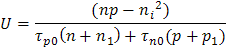
where n1, p1 are the numbers of carriers in recombination sites, n0, p0 are the electron and hole concentrations in equilibrium and τp0 and τn0 are the minority carrier lifetimes for holes and electrons.
In p-type material and under low injection (low bias) conditions, p >> n also p ≈ p0. Further, we will assume that n >> n1 and p >> p1 and that the lifetimes do not vary dramatically in n- and p-type material (i.e., that τn0p >> τp0n). The above equation then reduces to the recombination rate for electrons in p-type material as:
![]()
This is the low injection form of the recombination rate and it is commonly used in closed form solutions of pn junctions as it greatly simplifies the mathematics.
For holes in n-type material, ![]()
Finding the Generation Rate:
In general G will be given by the equation:
Generation Rate
where N0 = photon flux at the surface (photons/unit-area/sec.);
α = absorption coefficient; and
x = distance into the material.
Note that N0 may vary with time and may change with wavelength, such that in general N0 will be a function of time and wavelength denoted by N0( λ,t) , which also makes the generation rate G a function of wavelength and time. However, here we are solving only for steady state and ignore any time dependence. Wavelength dependence is often included by summing the result obtained at one wavelength over all wavelengths of interest. The exponential form of the generation rate generally makes the differential equation to be solved a nonhomogeneous second order differential equation. Therefore, approximation to the generation rate are often that the generation is constant (valid when the dimensions of interest are small compared to α-1), that there is an impulse generation at the surface, or that the generation is zero.
Finding the general solution
The general solution to the differential equation in (3a) and (3b) will depend on the equation for U and G. There are several common general solutions. These are shown below, where ![]() is any function dependent only on x, and for the pn junction equations
is any function dependent only on x, and for the pn junction equations ![]() will usually correspond to one of n(x), p(x), Δn(x) or Δp(x) . A and B are constants that need to be determined by the boundary conditions. C and K are semiconductor or device constants. C for pn junction equations is usually Ln or Lp (the minority carrier diffusions length) and K is often a constant generation term, G.
will usually correspond to one of n(x), p(x), Δn(x) or Δp(x) . A and B are constants that need to be determined by the boundary conditions. C and K are semiconductor or device constants. C for pn junction equations is usually Ln or Lp (the minority carrier diffusions length) and K is often a constant generation term, G.
|
Differential equation of the form |
General solution |
When used |
|
Bulk recombination, no generation |
||
|
Bulk recombination, constant geneneration |
||
|
Zero recombination and generation |
||
|
Zero recombination, constant generation |
Finding the particular solution (all equations will be for electrons in p-type material)
The particular solution depends on the conditions of each region at the edges or the regions. For many semiconductor devices, at least one edge will be a pn junction, and hence Boundary Condition ?1 below applies to many semiconductor devices.
- Boundary condition at the edge of a depletion region of a pn junction:
In p-type material: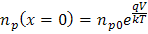 or
or 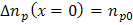
In n-type material: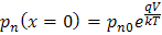 or
or 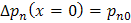
- Possible boundary conditions at a semiconductor surface
The other boundary condition may depend on the surface of the device. The surface recombination velocity, Sr, determines the conditions at the surface. Some common boundary conditions for surfaces are listed below for p-type material.
Location of surface
Boundary Description
Equation
Surface is far away from the junction (W>>Ln)
The minority carrier concentration must be finite as x -> ∞
n(x->∞) = finite
Surface is within a few diffusion lengths of junction
Surface recombination is “infinitely” fast (Sr = ∞) All carriers that reach the surface recombine.
Δn (x=W) = 0
Surface is within a few diffusion lengths of junction
Surface recombination is finite.
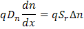
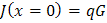
Surface next to a light generation source
Impulse light generation at surface with no surface recombination
Finding diffusion currents in Regions I and III
Once we have a form of n(x) and p(x) from the procedures described in 2(b) and 2(c), we can readily find the minority carrier currents by using the general equations:
 and
and ![]()
- Log in or register to post comments
- 1 comment(s)
 Español